×
ToyotaParts- Hello
- Login or Register
- Quick Links
- Live Chat
- Track Order
- Parts Availability
- RMA
- Help Center
- Contact Us
- Shop for
- Toyota Parts
- Scion Parts
My Garage
My Account
Cart
OEM 2002 Toyota Sequoia Alternator
Generator- Select Vehicle by Model
- Select Vehicle by VIN
Select Vehicle by Model
orMake
Model
Year
Select Vehicle by VIN
For the most accurate results, select vehicle by your VIN (Vehicle Identification Number).
1 Alternator found

 Product Specifications
- Other Name: Reman Alternator W/R
- Condition: New
- SKU: 27060-0F020-84
- Warranty: This genuine part is guaranteed by Toyota's factory warranty.
2002 Toyota Sequoia Alternator
Looking for affordable OEM 2002 Toyota Sequoia Alternator? Explore our comprehensive catalogue of genuine 2002 Toyota Sequoia Alternator. All our parts are covered by the manufacturer's warranty. Plus, our straightforward return policy and speedy delivery service ensure an unparalleled shopping experience. We look forward to your visit!
2002 Toyota Sequoia Alternator Parts Q&A
- Q: How to service and repair the alternator on 2002 Toyota Sequoia?A: Disassembling an alternator starts with removing the rear end cover through a procedure of first removing the nut and terminal insulator followed by the bolt and 3 nuts and plate terminal and end cover. Detach the brush holder after removing the brush holder cover combined with the 2 screws and the brush holder before taking off the seal plate from the rectifier end frame. First remove the voltage regulator by disturbing its three screws before moving on to the rectifier holder that requires you to uninstall its nut and cord clip and then unfasten four screws and rectifier holder and lastly extract the four rubber insulators. Special Service Tool 09820-63011 requires use with a torque wrench to secure the pulley and socket at 39 Nm (400 kgf.cm, 29 ft.lbf) when fastening the socket clockwise to rotor shaft. Mount the adapter on a vise and apply the socket with proper insertion before adding the pulley nut while rotating it counterclockwise only until half a turn is reached to protect the rotor shaft from damage. Detach the generator from its adapter while removing the pulley holding tool and socket and the pulley nut and pulley. You must start by loosening the 3 nuts securing the rectifier end frame and using Special Service Tool 09286-46011 to break its connection before removing the generator washer connected to the end frame. The reassembly begins by attaching the drive end frame to the pulley followed by rotor installation to the drive end frame. Lastly install the rectifier end frame by putting the generator washer on the rotor while using a 29 mm socket wrench to slowly press in the rectifier end frame together with 3 installed nuts tightened to 4.5 N.m (46 kgf.cm, 39 in.lbf). Hand-tighten the pulley nut first before applying the pulley holding tool with a torque wrench to reach 39 N.m clockwise torque (398 kg.cm, 29 ft.lb) while keeping the tool locked on the pulley shaft. Follow this procedure to connect the adapter to a vise and place the socket within it then introduce the pulley nut for clockwise torquing to 111 N.m (1,132 kg.cm, 82 ft.lb). Remove the generator from its adapter before removing both the socket along with the pulley holding tool. Secure the rectifier holder by applying 2.94 N.m (30 kgf.cm, 26 in.lbf) torque on its 4 screws after positioning the lead wire rubber insulators correctly and placing the rectifier unit. Fasten the cord clip using the nut at 5.4 N.m (55 kgf.cm, 48 in.lbf). Install the seal plate first on the rectifier end frame and then add the voltage regulator and brush holder facing the right direction before tightening the 5 screws at 1.96 N.m (20 kgf.cm, 17 in.lbf) and finishing with cover installation of the brush holder. The installation process ends with attaching the end cover together with the plate terminal using a bolt and three nuts at 3.85 N.m (39 kgf.cm, 34 in.lbf). At the same time, use a nut to secure the terminal insulator at 4.1 N.m (41.5 kgf.cm, 36 in.lbf). Test for smooth rotor rotation. Incident replacement calls for the uninstalling of the 4 screws and bearing retainer followed by bearing extraction with Special Service Tool 09950-60010 (09951-00260, 09952-6010). Installation of the new bearing requires this tool (09950-60010) along with reference tool (09951-00520) before screwing the bearing retainer down using 4 screws at 3.0 N.m (31 kgf.cm, 27 in.lbf). Special Service Tool 09820-00021 enables bearing cover (outside) and bearing removal with caution around the fan before removing bearing cover (inside) to place on rotor. Use Special Service Tool 09820-00031 to create bearing press while inserting a new bearing followed by bearing cover (outside) insertion through tool 09285-76010.
Related 2002 Toyota Sequoia Parts
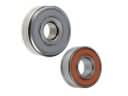 2002 Toyota Sequoia Alternator Bearing
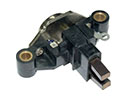 2002 Toyota Sequoia Alternator Brush
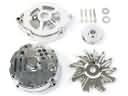 2002 Toyota Sequoia Alternator Case Kit
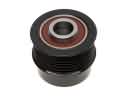 2002 Toyota Sequoia Alternator Pulley
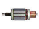 2002 Toyota Sequoia Armature
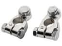 2002 Toyota Sequoia Battery Terminal
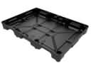 2002 Toyota Sequoia Battery Tray
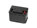 2002 Toyota Sequoia Car Batteries
 2002 Toyota Sequoia Starter Drive Gear
 2002 Toyota Sequoia Starter Motor
 2002 Toyota Sequoia Starter Solenoid
 2002 Toyota Sequoia Voltage Regulator