×
ToyotaParts- Hello
- Login or Register
- Quick Links
- Live Chat
- Track Order
- Parts Availability
- RMA
- Help Center
- Contact Us
- Shop for
- Toyota Parts
- Scion Parts
My Garage
My Account
Cart
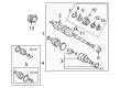
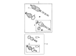
OEM 2003 Toyota Matrix Axle Shaft
Car Axle Shaft- Select Vehicle by Model
- Select Vehicle by VIN
Select Vehicle by Model
orMake
Model
Year
Select Vehicle by VIN
For the most accurate results, select vehicle by your VIN (Vehicle Identification Number).
15 Axle Shafts found

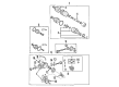
2003 Toyota Matrix Axle Assembly, Rear
Part Number: 42340-32111$347.51 MSRP: $496.17You Save: $148.66 (30%)Ships in 1-3 Business DaysProduct Specifications- Other Name: Shaft Assembly, Rear Drive; CV Axle Assembly, Rear Left, Rear Right; CV Axle Assembly; GSP Cv Axle; Axle Shaft
- Position: Rear
- Replaces: 42340-32110
- Condition: New
- SKU: 42340-32111
- Warranty: This genuine part is guaranteed by Toyota's factory warranty.

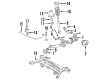
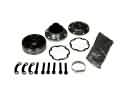
2003 Toyota Matrix Hub & Bearing, Passenger Side
Part Number: 43410-12250$279.58 MSRP: $403.29You Save: $123.71 (31%)Ships in 1-3 Business DaysProduct Specifications- Other Name: Wheel Hub Repair Kit; Wheel Bearing; Axle Bearing; Wheel Hub; Shaft Assembly, Front Drive, Passenger Side
- Position: Passenger Side
- Part Name Code: 43410
- Item Weight: 15.20 Pounds
- Item Dimensions: 29.8 x 7.3 x 6.4 inches
- Condition: New
- Fitment Type: Direct Replacement
- SKU: 43410-12250
- Warranty: This genuine part is guaranteed by Toyota's factory warranty.

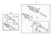
2003 Toyota Matrix Axle Assembly, Driver Side
Part Number: 43420-12590$404.50 MSRP: $592.80You Save: $188.30 (32%)Ships in 1-3 Business DaysProduct Specifications- Other Name: Shaft Assembly, Front Drive; CV Axle Assembly, Front Left; GSP Cv Axle; Axle Shaft; Axle; Shaft Assembly, Front Drive, Driver Side; CV Axle Assembly
- Position: Driver Side
- Part Name Code: 43420
- Item Weight: 18.20 Pounds
- Item Dimensions: 30.1 x 5.1 x 5.1 inches
- Condition: New
- Fitment Type: Direct Replacement
- SKU: 43420-12590
- Warranty: This genuine part is guaranteed by Toyota's factory warranty.

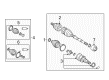
2003 Toyota Matrix Axle Assembly, Driver Side
Part Number: 43420-01070$387.86 MSRP: $568.41You Save: $180.55 (32%)Ships in 1-3 Business DaysProduct Specifications- Other Name: Shaft Assembly, Front Drive; CV Axle Assembly, Front Left; GSP Cv Axle; Axle Shaft; Axle; Shaft Assembly, Front Drive, Driver Side; CV Axle Assembly
- Position: Driver Side
- Part Name Code: 43420
- Item Weight: 14.90 Pounds
- Item Dimensions: 28.9 x 7.3 x 6.4 inches
- Condition: New
- Fitment Type: Direct Replacement
- SKU: 43420-01070
- Warranty: This genuine part is guaranteed by Toyota's factory warranty.
 Product Specifications
- Other Name: Shaft Assembly, Front Drive; CV Axle Assembly, Front Right; GSP Cv Axle; Axle Shaft; Axle; Shaft Assembly, Front Drive, Passenger Side; CV Axle Assembly
- Manufacturer Note: W(ABS)
- Position: Passenger Side
- Part Name Code: 43410
- Item Weight: 14.40 Pounds
- Item Dimensions: 29.5 x 7.3 x 6.5 inches
- Condition: New
- Fitment Type: Direct Replacement
- SKU: 43410-02280
- Warranty: This genuine part is guaranteed by Toyota's factory warranty.
- Product Specifications
- Other Name: Shaft Assembly, Front Drive; CV Axle Assembly, Front Right; GSP Cv Axle; Axle Shaft; Axle; Shaft Assembly, Front Drive, Passenger Side; CV Axle Assembly
- Manufacturer Note: W(ABS)
- Position: Passenger Side
- Part Name Code: 43410
- Item Weight: 25.30 Pounds
- Item Dimensions: 42.8 x 5.6 x 5.4 inches
- Condition: New
- Fitment Type: Direct Replacement
- SKU: 43410-02320
- Warranty: This genuine part is guaranteed by Toyota's factory warranty.
- Product Specifications
- Other Name: Shaft Assembly, Front Drive; CV Axle Assembly, Front Right, Rear Right; Axle Shaft; Axle; Shaft Assembly, Front Drive, Passenger Side
- Position: Passenger Side
- Part Name Code: 43410
- Item Weight: 24.30 Pounds
- Item Dimensions: 43.3 x 5.5 x 5.4 inches
- Condition: New
- Fitment Type: Direct Replacement
- SKU: 43410-01100
- Warranty: This genuine part is guaranteed by Toyota's factory warranty.

 Product Specifications
- Other Name: Shaft Assembly, Front Drive; CV Axle Assembly, Front Right; GSP Cv Axle; Axle Shaft; Axle; Shaft Assembly, Front Drive, Passenger Side; CV Axle Assembly
- Position: Passenger Side
- Part Name Code: 43410
- Item Weight: 17.70 Pounds
- Item Dimensions: 44.1 x 6.1 x 6.2 inches
- Condition: New
- Fitment Type: Direct Replacement
- SKU: 43410-02350
- Warranty: This genuine part is guaranteed by Toyota's factory warranty.
2003 Toyota Matrix Axle Assembly, Passenger Side
Part Number: 43410-02310$452.63 MSRP: $663.33You Save: $210.70 (32%)Product Specifications- Other Name: Shaft Assembly, Front Drive; CV Axle Assembly, Front Right; GSP Cv Axle; Axle Shaft; Axle; Shaft Assembly, Front Drive, Passenger Side; CV Axle Assembly
- Position: Passenger Side
- Part Name Code: 43410
- Item Weight: 20.20 Pounds
- Item Dimensions: 49.9 x 6.2 x 6.1 inches
- Condition: New
- Fitment Type: Direct Replacement
- SKU: 43410-02310
- Warranty: This genuine part is guaranteed by Toyota's factory warranty.
- Product Specifications
- Other Name: Shaft Assembly, Front Drive; CV Axle Assembly, Front Left, Rear Left; GSP Cv Axle; Axle Shaft; Axle; Shaft Assembly, Front Drive, Driver Side; CV Axle Assembly
- Position: Driver Side
- Part Name Code: 43420
- Item Weight: 15.40 Pounds
- Item Dimensions: 30.1 x 5.2 x 5.1 inches
- Condition: New
- Fitment Type: Direct Replacement
- SKU: 43420-01090
- Warranty: This genuine part is guaranteed by Toyota's factory warranty.
- Product Specifications
- Other Name: Shaft Assembly, Front Drive; CV Axle Assembly, Front Left; GSP Cv Axle; Axle Shaft; Axle; Shaft Assembly, Front Drive, Driver Side; CV Axle Assembly
- Manufacturer Note: W(ABS)
- Position: Driver Side
- Part Name Code: 43420
- Item Weight: 15.20 Pounds
- Item Dimensions: 29.2 x 7.5 x 6.5 inches
- Condition: New
- Fitment Type: Direct Replacement
- SKU: 43420-02390
- Warranty: This genuine part is guaranteed by Toyota's factory warranty.
- Product Specifications
- Other Name: Shaft Assembly, Front Drive; CV Axle Assembly, Front Right; GSP Cv Axle; Axle Shaft; Axle; Shaft Assembly, Front Drive, Passenger Side; CV Axle Assembly
- Position: Passenger Side
- Part Name Code: 43410
- Item Weight: 20.20 Pounds
- Item Dimensions: 43.3 x 5.7 x 5.6 inches
- Condition: New
- Fitment Type: Direct Replacement
- SKU: 43410-12630
- Warranty: This genuine part is guaranteed by Toyota's factory warranty.
- Product Specifications
- Other Name: Shaft Assembly, Front Drive; CV Axle Assembly, Front Left; GSP Cv Axle; Axle Shaft; Axle; Shaft Assembly, Front Drive, Driver Side; CV Axle Assembly
- Manufacturer Note: W(ABS)
- Position: Driver Side
- Part Name Code: 43420
- Item Weight: 15.10 Pounds
- Item Dimensions: 28.9 x 7.5 x 6.5 inches
- Condition: New
- Fitment Type: Direct Replacement
- SKU: 43420-01080
- Warranty: This genuine part is guaranteed by Toyota's factory warranty.
 Product Specifications
- Other Name: Shaft Assembly, Front Drive; Axle Shaft; Shaft Assembly, Front Drive, Passenger Side
- Position: Passenger Side
- Part Name Code: 43410
- Item Weight: 24.40 Pounds
- Item Dimensions: 42.4 x 5.5 x 5.4 inches
- Condition: New
- Fitment Type: Direct Replacement
- SKU: 43410-01090
- Warranty: This genuine part is guaranteed by Toyota's factory warranty.
- Product Specifications
- Other Name: Shaft Assembly, Front Drive; CV Axle Assembly, Front Left; GSP Cv Axle; Axle Shaft; Axle; Shaft Assembly, Front Drive, Driver Side; CV Axle Assembly
- Position: Driver Side
- Part Name Code: 43420
- Item Weight: 14.40 Pounds
- Item Dimensions: 29.5 x 7.3 x 6.4 inches
- Condition: New
- Fitment Type: Direct Replacement
- SKU: 43420-01050
- Warranty: This genuine part is guaranteed by Toyota's factory warranty.
2003 Toyota Matrix Axle Shaft
Looking for affordable OEM 2003 Toyota Matrix Axle Shaft? Explore our comprehensive catalogue of genuine 2003 Toyota Matrix Axle Shaft. All our parts are covered by the manufacturer's warranty. Plus, our straightforward return policy and speedy delivery service ensure an unparalleled shopping experience. We look forward to your visit!
2003 Toyota Matrix Axle Shaft Parts Q&A
- Q: How to Overhaul an Axle Shaft Assembly on 2003 Toyota Matrix?A: The first step for axle shaft assembly overhaul involves draining manual transaxle oil using 39.2 Nm torque and automatic transaxle fluid with 49 Nm torque. After applying vehicle brakes start by unstaking the front axle hub LH nut with hammer while using Special Service Tool: 09930-00010 and then detach the front wheel and engine under cover LH. To perform the procedure you should isolate the front stabilizer link assembly LH from the shock absorber assembly front LH then inspect the ball joint for movement and keep the stud fixed by using a hexagon wrench (6 mm). The procedure calls for removal of the speed sensor front LH coupled with the flexible hose between the shock absorber assembly front LH and steering knuckle. Separate the tie rod end sub-assembly LH through the use of Special Service Tool: 09628-62011 before extracting the front suspension arm sub-assembly lower No. 1 LH from its lower ball joint connection. A plastic hammer allows separation of the front drive shaft assembly LH from the front axle assembly LH without harming the boot and speed sensor rotor. You must remove the 2 bearing lock bolts on the front drive shaft assembly RHS to extract it using tools 09520-01010, 09520-24010 (09520-32040). Then pull the front drive shaft assemblies LH and RHS out of position. The hub bearing needs protection from damage through the use of Special Service Tool: 09608-16042 (09608-02021, 09608-02041) to support it during vehicle weight application. Check the front drive shaft assembly LH by evaluating joint outboard motion with minimal play and smooth motion in the inboard joint until they detect any damage to the boots through level inspection of the assembly. To begin separation between inboard joint boot and inboard joint sub-assembly LH you must first take off the inboard joint boot LH Number 2 clamp and the inboard joint boot LH clamp. The technician will extract old grease from the inboard joint sub-assembly LH while creating matchmarks before taking out the inboard joint sub-assembly LH from the outboard joint shaft assembly. A snap ring expander helps to remove the inner LH shaft snap ring before marking both the outboard joint shaft assembly and tripod joint assembly for disassembly with a brass bar and hammer taking care not to strike the roller. The service technician should disconnect the following parts for the inboard joint boot LH No. 2 clamp and inboard joint boot LH clamp and inboard joint boot. Cut the clamp that controls the setting and detach the damper which belongs to the drive shaft (M/T transaxle). The technician must cut the outboard joint boot LH No. 2 clamp alongside the outboard joint boot LH clamp before removing the outboard joint boot and its aged grease from the outboard joint. Special Service Tool: 09950-00020 and a press will be used for removing the LH hole snap ring and the dust cover LH but the inboard joint should not fall during the operation. A press must be used to extract both the bearing case sub-assembly and drive shaft bearing snap ring before removing the dust cover right hand with matching safety measures. To install a new drive shaft bearing use Special Service Tool: 09950-60010 (09951-00650) and 09950-70010 (09951-07100) along with a press. Then add new drive shaft bearing snap ring followed by bearing case sub-assembly application with a snap ring expander. The replacement dust covers require installation for both drive shafts at their proper position after the bearing case sub-assembly. After securing the outboard joint boot through its clamps check the resulting clearance which must be 0.8 mm (0.032 inch) or less. Assessing the drive shaft damper requires setting the necessary distance along with clamp tightening followed by a clearance measurement. Install the front drive inboard joint assembly LH after wrapping the spline with vinyl tape while installation and packing the inboard joint sub-assembly LH with grease. To finalize installation of the inboard joint boot users must secure its clamps before measuring the clearance. The front drive shaft assembly needs another examination for play and boot damage before installation of the LH and RH components with ATF for A/T and gear oil for M/T use, spline alignment, and appropriate torques. The front axle assembly LH should be installed without damaging its outboard joint boot or speed sensor rotor while the front suspension arm sub-assembly lower No. 1 LH and tie rod end sub-assembly LH receive their specified torque installation. Install the speed sensor front LH together with its flexible hose after maintaining both components clean and correctly aligned and then add the front stabilizer link assembly LH. End the procedure by screwing a new hub LH nut to 216 Nm (2,200 kgf-cm, 159 ft. lbs.) then staking it before reinstallation of the front wheel with necessary transaxle oils added during required inspections and adjustments completed before testing ABS speed sensor signal functionality.
Related 2003 Toyota Matrix Parts
 2003 Toyota Matrix CV Joint
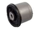 2003 Toyota Matrix Axle Beam Mount
 2003 Toyota Matrix Bump Stop
 2003 Toyota Matrix Coil Spring Insulator
 2003 Toyota Matrix Coil Springs
 2003 Toyota Matrix Control Arm Bushing
 2003 Toyota Matrix Lateral Link
 2003 Toyota Matrix Shock Absorber
 2003 Toyota Matrix Shock And Strut Mount
 2003 Toyota Matrix Suspension Strut Rod
 2003 Toyota Matrix Sway Bar Bushing
 2003 Toyota Matrix Sway Bar Kit