×
ToyotaParts- Hello
- Login or Register
- Quick Links
- Live Chat
- Track Order
- Parts Availability
- RMA
- Help Center
- Contact Us
- Shop for
- Toyota Parts
- Scion Parts
My Garage
My Account
Cart
OEM 2006 Toyota Sienna Antenna
Radio Antenna- Select Vehicle by Model
- Select Vehicle by VIN
Select Vehicle by Model
orMake
Model
Year
Select Vehicle by VIN
For the most accurate results, select vehicle by your VIN (Vehicle Identification Number).
3 Antennas found


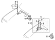
2006 Toyota Sienna Antenna Mast
Part Number: 86309-0C020$38.11 MSRP: $51.41You Save: $13.30 (26%)Ships in 1-3 Business DaysProduct Specifications- Other Name: Pole Sub-Assembly, Pull; Radio Antenna Assembly; Radio Antenna Mast; Antenna Assembly; Mast; Pole Sub-Assembly, Pull Top Antenna
- Replaces: 86309-42060, 86309-AA040, 86309-AA041, 86309-35100, 86309-42040, 86309-42041, 86309-AA042
- Part Name Code: 86309B
- Item Weight: 2.40 Pounds
- Item Dimensions: 36.4 x 4.2 x 4.2 inches
- Condition: New
- Fitment Type: Direct Replacement
- SKU: 86309-0C020
- Warranty: This genuine part is guaranteed by Toyota's factory warranty.


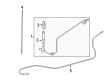
2006 Toyota Sienna Antenna Assembly
Part Number: 86300-AE010$69.19 MSRP: $94.13You Save: $24.94 (27%)Ships in 1-3 Business DaysProduct Specifications- Other Name: Antenna Assembly, With Holder; Radio Antenna Assembly; Antenna; Antenna Assembly, W/Holder
- Part Name Code: 86300
- Item Weight: 0.90 Pounds
- Item Dimensions: 15.6 x 11.3 x 3.0 inches
- Condition: New
- Fitment Type: Direct Replacement
- SKU: 86300-AE010
- Warranty: This genuine part is guaranteed by Toyota's factory warranty.

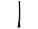
2006 Toyota Sienna Antenna Assembly
Part Number: 86300-AE021$90.98 MSRP: $127.72You Save: $36.74 (29%)Ships in 1-3 Business DaysProduct Specifications- Other Name: Antenna Assembly, Amplifier; Radio Antenna Mast; Antenna; Antenna Assembly, W/Holder
- Part Name Code: 86300
- Item Weight: 2.40 Pounds
- Item Dimensions: 26.3 x 5.3 x 5.3 inches
- Condition: New
- Fitment Type: Direct Replacement
- SKU: 86300-AE021
- Warranty: This genuine part is guaranteed by Toyota's factory warranty.
2006 Toyota Sienna Antenna
Looking for affordable OEM 2006 Toyota Sienna Antenna? Explore our comprehensive catalogue of genuine 2006 Toyota Sienna Antenna. All our parts are covered by the manufacturer's warranty. Plus, our straightforward return policy and speedy delivery service ensure an unparalleled shopping experience. We look forward to your visit!
2006 Toyota Sienna Antenna Parts Q&A
- Q: How to remove and install the navigation antenna on 2006 Toyota Sienna?A: Start by finding the correct fasteners in the bolt, screw, and nut table before removing the navigation antenna. Start your process by disconnecting the battery negative terminal, taking off lower No.2 and lower No.3 parts of steering wheel cover, the horn button assembly, steering wheel assembly, steering column cover, headlight dimmer switch assembly, and windshield wiper switch assembly. First separate the instrument cluster finish panel by pulling its 2 clips to the rear. Then remove the combination meter using 4 screws and disconnect all connections. Untap the lower LH part of the instrument panel finish panel sub-assembly by removing 2 bolts and disconnecting the hood lock control cable assembly then releasing 2 claws and 3 clips before disconnecting all connectors. Take out 4 bolt screws and disengage the connector to remove the instrument panel safety pad insert sub-assembly No.1. After disconnecting the glove compartment door stopper sub-assembly from its claw, push the glove compartment door assembly walls to release the stoppers before pulling it back. Lift up both instrument side panel edges to take out the panel dolls No.2 which releases via 2 claws and 4 clips. First remove Installment Panel parts Number One and Three before taking off Floor Carpet panels (middle area of Left and Right sides) by releasing attachment holders. Use a moulding remover to open 3 clips and disconnect the connector to access the instrument cluster finish panel center No.1. This leads to continued disconnection of claws to take out the instrument cluster finish panel center No.2 and other sub-assemblies. Cut screw and unfasten five clips when removing the instrument cluster finish panel assembly center. Disable its claw and connection parts before taking out clips and bolts from the instrument cluster finish panel sub-assembly lower center. Pull the component rearward to disconnect the connector. A moulding remover frees clips and claws to take the stereo component speakers out when you remove 2 screws and disconnect the connector. Take out the navigation receiver, integration control and panel combination as well as the front pillar garnish pieces from both sides and instrument panel speaker sub-assemblies. Take off the front No.1 and No.2 speaker assemblies by unscrewing and disconnecting all connectors before removing the defroster nozzle opening plate No.1 using claws and its connector. Remove the instrument panel safety pad sub-assembly after disconnecting connectors and taking out bolts, screws and a nut. Free three clamps before taking out two screws to take the navigation antenna assembly away. Begin the process by installing the navigation antenna assembly before proceeding with the instrument panel safety pad sub-assembly through bolt using a torque wrench at 20 N.m tightening power. Lastly, set the shift lever assembly into position with 4 bolts tightened to 21 N.m. Continue with the installation of the defroster nozzle opening plate No.1, front No.2 and No.1 speaker assemblies, instrument panel speaker panel sub-assemblies, front pillar garnishes (RH and LH), integration control and panel assembly, navigation receiver assembly, stereo component speaker assembly, instrument cluster finish panel garnish, instrument cluster finish panel sub-assembly lower center, instrument cluster finish panel assembly center, floor shift position indicator housing assembly, shift lever knob sub-assembly, instrument cluster finish panel centers No.2 and No.1, floor carpet covers (center RH and LH), instrument panel register assemblies No.3 and No.1, instrument side panels (RH and LH), instrument panel box No.2, glove compartment door assembly, glove compartment door stopper sub-assembly, instrument panel safety pad insert sub-assembly No.1, instrument panel finish panel sub-assembly lower LH, cowl side trim boards (RH and LH), front door scuff plates (RH and LH), combination meter assembly, instrument cluster finish panel sub-assembly, windshield wiper switch assembly, headlight dimmer switch assembly, spiral cable sub-assembly, steering column cover, adjusting the spiral cable sub-assembly, steering wheel assembly, horn button assembly, steering wheel cover lower No.2 and lower No.3, reconnect the battery negative terminal, and inspect the horn button assembly and SRS warning light.
Related 2006 Toyota Sienna Parts
 2006 Toyota Sienna Antenna Mast
 2006 Toyota Sienna Horn
 2006 Toyota Sienna ABS Relay
 2006 Toyota Sienna Antenna Cable
 2006 Toyota Sienna Body Control Module
 2006 Toyota Sienna Car Key
 2006 Toyota Sienna Daytime Running Light Relay
 2006 Toyota Sienna Ignition Lock Assembly
 2006 Toyota Sienna Ignition Lock Cylinder
 2006 Toyota Sienna Relay
 2006 Toyota Sienna Relay Block
 2006 Toyota Sienna Transmitter