×
ToyotaParts- Hello
- Login or Register
- Quick Links
- Live Chat
- Track Order
- Parts Availability
- RMA
- Help Center
- Contact Us
- Shop for
- Toyota Parts
- Scion Parts
My Garage
My Account
Cart
OEM Scion Heater Core
HVAC Heater Core- Select Vehicle by Model
- Select Vehicle by VIN
Select Vehicle by Model
orMake
Model
Year
Select Vehicle by VIN
For the most accurate results, select vehicle by your VIN (Vehicle Identification Number).
8 Heater Cores found

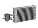
Scion Unit Sub-Assembly, Heater Radiator
Part Number: 87107-02230$293.57 MSRP: $419.14You Save: $125.57 (30%)Ships in 1-3 Business DaysProduct Specifications- Other Name: Unit Sub-Assembly, Radiator; HVAC Heater Core; Heater Core
- Replaces: 87107-42170

Scion Heater Core
Part Number: 87107-74010$322.67 MSRP: $460.70You Save: $138.03 (30%)Ships in 1-3 Business DaysProduct Specifications- Other Name: Unit Sub-Assembly, Radiator; HVAC Heater Core; Unit Sub-Assembly, Heater Radiator

Scion Heater Core
Part Number: 87107-52061$293.57 MSRP: $419.14You Save: $125.57 (30%)Ships in 1-3 Business DaysProduct Specifications- Other Name: Unit Sub-Assembly, Radiator; HVAC Heater Core; Unit Sub-Assembly, Heater Radiator
Scion Heater Core
Part Number: 87107-52060$357.20 MSRP: $523.47You Save: $166.27 (32%)Ships in 1-3 Business DaysProduct Specifications- Other Name: Unit Sub-Assembly, Radiator; HVAC Heater Core; Unit Sub-Assembly, Heater Radiator
- Replaces: 87107-0D051

Scion Heater Core
Part Number: 87107-21020$356.38 MSRP: $522.28You Save: $165.90 (32%)Ships in 1-3 Business DaysProduct Specifications- Other Name: Unit Sub-Assembly, Radiator; HVAC Heater Core; Unit Sub-Assembly, Heater Radiator

 Product Specifications
- Other Name: Unit Sub-Assembly, Radiator; HVAC Heater Core
- Replaces: 87107-52030

 Product Specifications
- Other Name: Heater Core Complete; HVAC Heater Core; Unit Sub-Assembly, Heater Radiator

 Product Specifications
- Other Name: Unit Sub-Assembly, Radiator; HVAC Heater Core; Unit Sub-Assembly, Heater Radiator
Scion Heater Core
Choose genuine Heater Core that pass strict quality control tests. You can trust the top quality and lasting durability. Shopping for OEM Heater Core for your Scion ? Our website is your one-stop destination. We stock an extensive selection of genuine Scion parts. The price is affordable so you can save more. It only takes minutes to browse and find the exact fit. Easily add to cart and check out fast. Our hassle-free return policy will keep you stress-free. We process orders quickly for swift delivery. Your parts will arrive faster, so you can get back on the road sooner.
Scion Heater Core Parts and Q&A
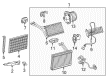
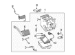
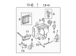
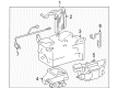
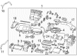
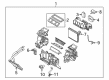
- Q: How to service and repair the heater core on Scion xB?A:The refrigerant discharge process for refrigeration system service starts with Special Service Tool: 09870-00015 07110-58060 (07117-58080, 07117-58090, 07117-78050, 07117-88060, 07117-88070, 07117-88080). Follow up by removing suction hose sub-assembly and the liquid tube sub-assembly A with Special Service Tool: 09870-00025. Disconnect the suction hose sub-assembly and the liquid tube sub-assembly A using Special Service Tool: 09870-00025 and then remove the heater water inlet hose A with pliers. Follow the same procedure to disconnect the heater water outlet hose A from its installation. First remove the heater control knob and then proceed to remove the instrument cluster finish panel sub-assembly CTR followed by the instrument panel sub-assembly w/passenger Air Bag assembly and the instrument panel assembly lower w/instrument panel reinforcement. Disassembly of the defroster nozzle assembly needs the removal of its retaining clip followed by disconnecting two claws. The procedure requires you to detach the ECM as well as the air conditioning blower assembly and both the outer and inner cables from the defroster damper control cable sub-assembly and air mix damper control cable sub-assembly. Detach air duct rear No.2 and air duct rear No.1 by the same procedure. The heater radiator assembly removal requires disconnecting three connectors and unfastening both a bolt and earth bolt from PTC heater before removing two nuts. To access the air duct assembly you must first disengage 4 claws before you can remove the heater cover by unscrewing its 2 clawed retainers. The thermistor assembly and cooler wiring No.2 both require removal through a process of unscrewing 5 screws and disengaging the claw followed by taking off the clamp. Unscrew the bracket from the heater radiator unit sub-assembly while also removing the clamp and disconnecting its connector. Insert and set the FACE position on the defroster damper control cable sub-assembly while securing both inner and outer cables before checking for correct performance. Perform the same installation procedure for the air mix damper control cable sub-assembly during MAX operation. COOL position. The service procedure involves placement of the ECM followed by assembly of instrument panel lower, instrument panel reinforcement, passenger Air Bag assembly and instrument cluster end. Add heater control knob last. Follow these steps to install sub-assembly A of the liquid tube along with sub-assembly B of the suction hose followed by engine coolant addition and refrigerant charging using Special Service Tool: 07110-58060 (07117-58060, 07117-58070, 07117-58080, 07117-58090, 07117-78050, 07117-88060, 07117-88070, 07117-88080). The tool requires a specified amount of 380 plus or minus 30 g (13.9 plus or minus 1.1 oz.). Before concluding the process you should warm up the engine and examine coolant leaks then check refrigerant levels.