×
ToyotaParts- Hello
- Login or Register
- Quick Links
- Live Chat
- Track Order
- Parts Availability
- RMA
- Help Center
- Contact Us
- Shop for
- Toyota Parts
- Scion Parts
My Garage
My Account
Cart
OEM Scion xB Blend Door Actuator
Air Blend Door Actuator- Select Vehicle by Model
- Select Vehicle by VIN
Select Vehicle by Model
orMake
Model
Year
Select Vehicle by VIN
For the most accurate results, select vehicle by your VIN (Vehicle Identification Number).
2 Blend Door Actuators found

Scion xB Servo
Part Number: 87106-02210$135.82 MSRP: $192.27You Save: $56.45 (30%)Ships in 1-3 Business Days


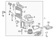
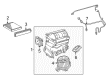
Scion xB Blend Door Actuator
Choose genuine Blend Door Actuator that pass strict quality control tests. You can trust the top quality and lasting durability. Shopping for OEM Blend Door Actuator for your Scion xB? Our website is your one-stop destination. We stock an extensive selection of genuine Scion xB parts. The price is affordable so you can save more. It only takes minutes to browse and find the exact fit. Easily add to cart and check out fast. Our hassle-free return policy will keep you stress-free. We process orders quickly for swift delivery. Your parts will arrive faster, so you can get back on the road sooner.
Scion xB Blend Door Actuator Parts and Q&A
- Q: How to service and repair the Blend Door Actuator / Motor on Scion xB?A:The Air Door Actuator / Motor repair process demands initial removal of the instrument panel sub-assembly and then removal of the lower instrument panel assembly after removing the instrument panel. The first step disconnects the connector and then removes three screws to withdraw the damper servo sub-assembly. The first step for installation involves attaching the damper servo with 3 screws while restoring the connector connections. Installation begins with first restoring the instrument panel to its position and afterward installing the instrument panel sub-assembly.
- Q: How to install a Blend Door Actuator and its related components on Scion xB?A:Installation of the air inlet control servo motor requires you to secure it with 2 screws. Install the blower assembly afterward you should put in place the No. 2 air duct sub-assembly. First tighten the air conditioning unit temporarily and afterwards install the instrument panel reinforcement assembly for automatic and manual transaxles. The installation sequence involves adding the air conditioning unit followed by instrument panel wire then drain cooler hose and power steering ECU assembly after which you should attach rear No. 2 air duct followed by instrument panel brace sub-assembly then relay block assembly before balancing it with No. 1 air duct sub-assembly and center instrument panel to cowl brace followed by lower defroster nozzle assembly then rear No. 1 air duct and finally rear No. 3 air duct. Install the steering column assembly while making sure both front wheels point toward the same direction as the vehicle faces forward. After connecting the No. 2 steering intermediate shaft assembly you must install the silencer sheet on the column hole cover while confirming the front wheels remain straight. After installing the turn signal switch assembly with spiral cable sub-assembly it is necessary to add the steering column cover. The spiral cables require adjustment before you can fit the steering wheel assembly as well as the steering pad. Connect together all assembly parts consisting of lower instrument panel sub-assembly, antenna cord sub-assembly, hood lock control lever sub-assembly, No. 1 instrument cluster finish panel seal, radio bracket, instrument panel sub reinforcement, instrument panel finish lower panel sub-assembly, and No. 1 switch hole base. The connection of air mix damper control cable sub-assembly with No. 2 heater control cable sub-assembly must be performed before fitting the air conditioning panel assembly. Natural gearboxes require the installation of the shift lever assembly while the transmission control cable assembly needs connection until the shift lever receives proper position adjustment checks. Both manual transaxle procedures require installing the shift lever assembly along with transmission control cable assembly installation before transmission control cable adjustment. The manufacturing process requires installation of the instrument panel finish lower panel together with front No. 1 console box insert, front No. 2 console box insert, instrument cluster finish center lower panel and shift lever knob sub-assembly for manual transaxles. Backward installation requires cowl side trim boards (RH and LH) and front door scuff plates (RH and LH) whereas the instrument panel receives its upper sub-assembly and glove compartment door assembly and combination meter assembly together with instrument cluster finish panel assembly and its lower and center panel sub-assemblies. Place the front pillar garnishes on both sides and install the front door opening trim Weather Strips (also on both sides) before inspecting the steering pad and checking the location of the center point between the steering wheel and pad. Install the water hoses to heater outlets then connect the air conditioning tube with its accessory assembly and suction pipe sub-assembly. Add refrigerant pressure together with engine coolant to the system while applying 5.4 Nm of torque on the negative battery cable. The technician should first inspect for coolant leaks before proceeding to initialize the rotation angle sensor while calibrating the torque sensor zero point. Check the SRS warning light and perform engine heating while inspecting for refrigerant pipe breakdowns.


Related Scion xB Parts
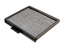 Scion xB Cabin Air Filter
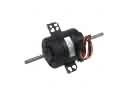 Scion xB Blower Motor
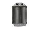 Scion xB Heater Core
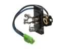 Scion xB Blower Motor Resistor
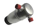 Scion xB A/C Accumulator
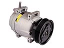 Scion xB A/C Compressor
 Scion xB A/C Condenser
 Scion xB A/C Expansion Valve
 Scion xB A/C Hose
 Scion xB Ambient Temperature Sensor
 Scion xB Evaporator
 Scion xB HVAC Pressure Switch