×
ToyotaParts- Hello
- Login or Register
- Quick Links
- Live Chat
- Track Order
- Parts Availability
- RMA
- Help Center
- Contact Us
- Shop for
- Toyota Parts
- Scion Parts
My Garage
My Account
Cart
OEM Toyota Corolla Shift Cable
Transmission Shift Cable- Select Vehicle by Model
- Select Vehicle by VIN
Select Vehicle by Model
orMake
Model
Year
Select Vehicle by VIN
For the most accurate results, select vehicle by your VIN (Vehicle Identification Number).
14 Shift Cables found


Toyota Corolla Shift Control Cable
Part Number: 33820-02A40$241.26 MSRP: $344.46You Save: $103.20 (30%)Ships in 1-3 Business Days

Toyota Corolla Cable Assembly
Part Number: 33820-02600$258.50 MSRP: $369.08You Save: $110.58 (30%)Ships in 1-2 Business Days
Toyota Corolla Shift Control Cable
Part Number: 33820-02581$404.73 MSRP: $593.14You Save: $188.41 (32%)
Toyota Corolla Shift Control Cable
Part Number: 33820-12J30$173.30 MSRP: $245.32You Save: $72.02 (30%)Ships in 1-3 Business Days
Toyota Corolla Shift Control Cable
Part Number: 33820-02A50$165.78 MSRP: $234.69You Save: $68.91 (30%)Ships in 1-3 Business DaysToyota Corolla Shift Control Cable
Part Number: 33820-02A10$166.13 MSRP: $235.19You Save: $69.06 (30%)Ships in 1-3 Business DaysToyota Corolla Shift Control Cable
Part Number: 33820-12J60$220.76 MSRP: $315.19You Save: $94.43 (30%)Ships in 1-3 Business Days
Toyota Corolla Control Cable
Part Number: 33820-12J20$337.49 MSRP: $481.86You Save: $144.37 (30%)Ships in 1-3 Business Days
Toyota Corolla Control Cable
Part Number: 33820-02830$293.22 MSRP: $418.66You Save: $125.44 (30%)Ships in 1-3 Business DaysToyota Corolla Shift Control Cable
Part Number: 33820-12J50$173.30 MSRP: $245.32You Save: $72.02 (30%)Ships in 1-3 Business DaysToyota Corolla Shift Control Cable
Part Number: 33820-02610$260.37 MSRP: $371.75You Save: $111.38 (30%)Ships in 1-3 Business Days
Toyota Corolla Shift Control Cable
Part Number: 33820-02590$370.91 MSRP: $543.56You Save: $172.65 (32%)
Toyota Corolla Shift Control Cable
Part Number: 33820-12K00$220.76 MSRP: $315.19You Save: $94.43 (30%)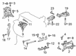
Toyota Corolla Shift Control Cable
Part Number: 33820-02860$187.90 MSRP: $268.28You Save: $80.38 (30%)
Toyota Corolla Shift Cable
Choose genuine Shift Cable that pass strict quality control tests. You can trust the top quality and lasting durability. Shopping for OEM Shift Cable for your Toyota Corolla? Our website is your one-stop destination. We stock an extensive selection of genuine Toyota Corolla parts. The price is affordable so you can save more. It only takes minutes to browse and find the exact fit. Easily add to cart and check out fast. Our hassle-free return policy will keep you stress-free. We process orders quickly for swift delivery. Your parts will arrive faster, so you can get back on the road sooner.
Toyota Corolla Shift Cable Parts and Q&A
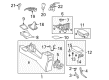
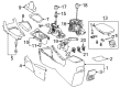
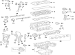
- Q: How to remove the shift cable from the U341E automatic transmission/transaxle on Toyota Corolla?A:The removal process for the shift cable from U341E automatic transmission/transaxle begins by taking away the lower instrument panel finish panels from both sides before moving to the shift lever knob sub-assembly and continuing with center No. 1 instrument cluster finish panel assembly and instrument panel box assembly and finalizing with both front console box inserts. The next step requires the removal of upper console panel sub-assembly together with console box carpet and console box assembly. You should remove the air cleaner case followed by the air cleaner cap sub-assembly and then the No. 2 cylinder head cover. One should first remove the engine under cover LH and the front Exhaust Pipe assembly. The front No. 1 floor heat insulator requires detachment after unfastening its 3 mounting nuts. Use setting N on the shift lever before removing the transmission control cable assembly end from the shift lever assembly. A screwdriver should be used to extract the stopper of the transmission control cable while making sure the stopper stays intact. Use a counter-clockwise rotation of the nut to the point of 180 degrees while applying pressure for removing the transmission control cable from the shift lever retainer avoiding excessive nut rotation. The removal of the clip allows the transmission control cable assembly to disconnect from the control cable bracket and allows the removal of the nut and assembly from the control shaft lever. The procedure begins with removing the nut so the transmission control cable assembly support can be detached from the rear engine mounting insulator while the subsequent step involves removing two nuts to disconnect the transmission control cable assembly from the body structure. The transmission control cable assembly should be pulled out of its body connection.
- Q: How to Properly Install a Shift Cable for U341E Automatic Transmission on Toyota Corolla?A:The installation process begins by confirming the park/neutral position switch and shift lever position is set to N. After placing the transmission control cable inside the cabin attach the 2 nuts while torqueing them to 5.0 Nm (51 kgf-cm, 44 in-lbf). Scatter the transmission control cable bracket onto the rear engine mounting insulator through a nut which requires 5.0 Nm (51 kgf-cm, 44 in-lbf) torque. Fasten the new clip to the transmission control cable bracket before connecting it to the control shaft lever through a nut torqued at 12 Nm (122 kgf-cm, 9 ft-lbf). After turning the transmission control cable nut 180 degrees counterclockwise users should maintain its position before pushing in the stopper until it clicks twice. The cable outer segment should be installed at the shift lever retainer while maintaining the spring at position "A." The stopper requires a gentle clockwise rotation of the nut when it can't be fully pushed in. Use the cable end to attach the shift lever assembly while drawing up the lock piece and simultaneously pushing the cable end to the base of the pin before pushing the lock piece securely into the adjuster case. Torque the three nuts attaching the front No. 1 floor heat insulator to 5.5 Nm (56 kgf-cm, 49 in-lbf). The installation sequence includes front Exhaust Pipe assembly and engine under cover LH along with air cleaner case and air cleaner cap sub-assembly followed by the No. 2 cylinder head cover and console box assembly, console box carpet, upper console panel sub-assembly, front No. 1 console box insert, front No. 2 console box insert, instrument panel box assembly, center No. 1 instrument cluster finish panel assembly, shift lever knob sub-assembly, lower instrument panel finish panel LH, and lower instrument panel finish panel RH. The inspector should check and reposition the shift lever if needed during the final step.


Related Toyota Corolla Parts
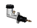 Toyota Corolla Clutch Master Cylinder
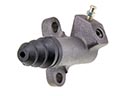 Toyota Corolla Clutch Slave Cylinder
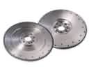 Toyota Corolla Flywheel
 Toyota Corolla Torque Converter
 Toyota Corolla Transmission Pan
 Toyota Corolla Automatic Transmission Filter
 Toyota Corolla Automatic Transmission Shift Levers
 Toyota Corolla Clutch Hose
 Toyota Corolla Clutch Slave Repair Kit
 Toyota Corolla Pressure Plate
 Toyota Corolla Release Bearing
 Toyota Corolla Transfer Case