×
ToyotaParts- Hello
- Login or Register
- Quick Links
- Live Chat
- Track Order
- Parts Availability
- RMA
- Help Center
- Contact Us
- Shop for
- Toyota Parts
- Scion Parts
My Garage
My Account
Cart
OEM Toyota Echo Alternator
Generator- Select Vehicle by Model
- Select Vehicle by VIN
Select Vehicle by Model
orMake
Model
Year
Select Vehicle by VIN
For the most accurate results, select vehicle by your VIN (Vehicle Identification Number).
4 Alternators found


Toyota Echo Alternator
Part Number: 27060-21031-84$144.24 MSRP: $189.72You Save: $45.48 (24%)Ships in 1-3 Business DaysToyota Echo Alternator
Part Number: 27060-21020-84$229.12 MSRP: $325.53You Save: $96.41 (30%)Ships in 1-3 Business DaysToyota Echo Alternator
Part Number: 27060-21042$441.50 MSRP: $647.03You Save: $205.53 (32%)Ships in 1-3 Business Days
Toyota Echo Alternator
Choose genuine Alternator that pass strict quality control tests. You can trust the top quality and lasting durability. Shopping for OEM Alternator for your Toyota Echo? Our website is your one-stop destination. We stock an extensive selection of genuine Toyota Echo parts. The price is affordable so you can save more. It only takes minutes to browse and find the exact fit. Easily add to cart and check out fast. Our hassle-free return policy will keep you stress-free. We process orders quickly for swift delivery. Your parts will arrive faster, so you can get back on the road sooner.
The Alternator which is Discover in the Toyota Echo is SMP at a built-in charger for the vehicles battery and provides power to electrical device when the vehicle is running. Located ahead of the engine, it collects mechanical energy from the engine then using a belt that is connected to the crankshaft, it produces electrical energy for the distribution of all other parts inclusive of the battery. To discharge and charge the battery and also supply the car's electrical system with electricity, the alternator uses a rotating magnetic field and a stationary armature to produce AC current. Due to the capability it has to regulate voltage so that it does not be below or above the minimum amount needed to charge the battery, the alternator is crucial in handling the power needs in a vehicle. Also, there is a high output version of alternators for cars that have more electrical burden for proper operation that increases reliability of extra accessorized cars.
Toyota Echo Alternator Parts and Q&A
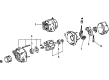
- Q: How to service and repair the alternator on Toyota Echo?A:Disassembly of the alternator starts with the removal of rear end cover components which include the nut and terminal insulator followed by the bolt and three nuts and plate terminal and end cover. Start by taking off the seal plate from the rectifier end frame after removing the brush holder and voltage regulator through a process which includes the brush holder cover followed by 5 screws and brush holder and voltage regulator. The rectifier holder requires disassembly through removal of 4 screws and holder and then 4 rubber insulators. Use Special Service Tool 09820-63010 while holding the tool with a torque wrench to tighten its socket clockwise until it reaches 39 Nm (400 kgf.cm, 29 ft.lbf) while making sure the tool remains secured to the rotor shaft. Place the adapter into a mounted vise while sliding in the socket and attaching the pulley nut and carefully loosen the nut in the counterclockwise direction just over half a turn to prevent rotor shaft damage. Conclude the generator adapter procedure by detaching the socket and pulley holding tool through socket rotation and discarding the pulley nut and pulley. First remove the four nuts while you unfasten the wire clip on the rectifier end frame then employ Special Service Tool 09286 - 46011 to detach the frame before taking out the generator washer from the rotor. The first step for reassembly requires the placement of the rectifier end frame onto the pulley before installing the rotor onto the drive end frame. Use the 29 mm socket wrench and press to install the rectifier end frame cautiously until it reaches proper torque values where Nut A requires 4.5 Nm (46 kg.cm, 40 in.lb) and Nut B needs 5.4 Nm (55 kg.cm, 48 in.lb). Apply hand power to the nut before using the pulley holding tool with a torque wrench to turn the socket clockwise to 39 N.m (400 kg.cm, 29 ft.lb) while maintaining secure attachment to the pulley shaft. First secure the adapter in a vise after inserting the socket then fasten the pulley nut but do it in a clockwise direction to 111 N.m (1,132 kg.cm, 82 ft.lb). Finally remove the generator from the adapter when completed. Secure the rectifier holder by placing rubber insulators onto the wires then fitting it by screwing 4 times with 2.9Nm (30kg.cm, 26in.lb) torque. First place the seal plate on the rectifier end frame before positioning the voltage regulator and brush holder in the correct orientation and installing 5 screws with 2.0 Nm (20 kg.cm, 18 in.lb) torque followed by applying the brush holder cover on the holder. You will finish the installation by attaching the end cover and plate terminal using the bolt and 3 nuts while tightening Nut 4.4 Nm (45 kg.cm, 39 in.lb) and Bolt 3.9 Nm (39 kg.cm, 35 in.lb). Afterward, install the terminal insulator by tightening the nut to 4.1 Nm (42 kg.cm, 36 in.lb). Test the rotor for normal movement without any obstruction.
- Q: How to remove and install an alternator on Toyota Echo?A:The procedure to remove the generator starts with unplugging the wire clamp from the wire clip on the rectifier end frame followed by removing the rubber cap and nut to disconnect the generator wire. The setup includes two steps where users separate the generator connector from the generator along with the harness clamp. Start by removing the Drive Belt after loosening its two bolts then remove the generator by unfastening the two securing bolts. Begin by setting up the generator before torqueing its 2 bolts just loosely. Follow drive belt installation by adjusting its tension to achieve correct torque values of 14 mm head 18 N.m (185 kgf.cm, 14 ft.lbf) and 17 mm head 54 N.m (550 kgf.cm, 40 ft.lbf). Attach the generator connector and harness clamp after connecting the generator wire with proper installation of the nut and rubber cap. The last step involves connecting the generator wire followed by installing both rubber cap and nut.


Related Toyota Echo Parts
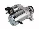 Toyota Echo Starter Motor
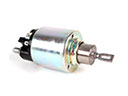 Toyota Echo Starter Solenoid
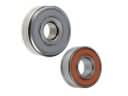 Toyota Echo Alternator Bearing
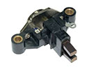 Toyota Echo Alternator Brush
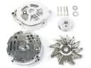 Toyota Echo Alternator Case Kit
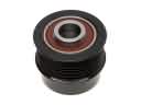 Toyota Echo Alternator Pulley
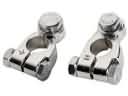 Toyota Echo Battery Terminal
 Toyota Echo Battery Tray
 Toyota Echo Car Batteries
 Toyota Echo Starter Brush
 Toyota Echo Starter Drive Gear
 Toyota Echo Voltage Regulator