×
ToyotaParts- Hello
- Login or Register
- Quick Links
- Live Chat
- Track Order
- Parts Availability
- RMA
- Help Center
- Contact Us
- Shop for
- Toyota Parts
- Scion Parts
My Garage
My Account
Cart
OEM Toyota Tundra Parking Brake Cable
Emergency Parking Brake Release Cable- Select Vehicle by Model
- Select Vehicle by VIN
Select Vehicle by Model
orMake
Model
Year
Select Vehicle by VIN
For the most accurate results, select vehicle by your VIN (Vehicle Identification Number).
16 Parking Brake Cables found


Toyota Tundra Rear Cable
Part Number: 46420-0C011$118.90 MSRP: $168.31You Save: $49.41 (30%)Ships in 1-3 Business Days


Toyota Tundra Front Cable
Part Number: 46410-34140$87.80 MSRP: $123.23You Save: $35.43 (29%)Ships in 1-3 Business Days
Toyota Tundra Front Cable
Part Number: 46410-34110$77.61 MSRP: $108.94You Save: $31.33 (29%)Ships in 1 Business Day


Toyota Tundra Front Cable
Part Number: 46410-34060$68.24 MSRP: $95.80You Save: $27.56 (29%)Ships in 1-3 Business Days
Toyota Tundra Front Cable
Part Number: 46410-0C011$56.51 MSRP: $78.66You Save: $22.15 (29%)Ships in 1-3 Business DaysToyota Tundra Rear Cable
Part Number: 46420-0C041$115.05 MSRP: $161.49You Save: $46.44 (29%)Ships in 1-3 Business DaysToyota Tundra Front Cable
Part Number: 46410-34130$78.55 MSRP: $110.27You Save: $31.72 (29%)Ships in 1-2 Business DaysToyota Tundra Front Cable
Part Number: 46410-34090$76.30 MSRP: $107.10You Save: $30.80 (29%)Ships in 1-3 Business Days
Toyota Tundra Front Cable
Part Number: 46410-0C021$66.59 MSRP: $93.47You Save: $26.88 (29%)Ships in 1-3 Business Days


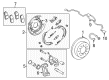
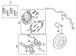
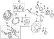
Toyota Tundra Parking Brake Cable
Choose genuine Parking Brake Cable that pass strict quality control tests. You can trust the top quality and lasting durability. Shopping for OEM Parking Brake Cable for your Toyota Tundra? Our website is your one-stop destination. We stock an extensive selection of genuine Toyota Tundra parts. The price is affordable so you can save more. It only takes minutes to browse and find the exact fit. Easily add to cart and check out fast. Our hassle-free return policy will keep you stress-free. We process orders quickly for swift delivery. Your parts will arrive faster, so you can get back on the road sooner.
The Toyota Tundra Parking Brake Cable is one of the Tundra's key components that help in commanding the parking brake - a safety feature that locks the car's wheels, especially on a slope. With this model, that has been highly appreciated for its quality and efficiency, the parking brake cable ensures the vehicle's connection between the parking brake and the entire braking system to ensure that it does not roll off on its own. Suitable for most Toyota Tundra models of the first and second generation, the parking brake cable is made to last, improving the car's functionality and safety. It is recommended to inspect and maintain its Parking Brake Cable often as a loose or stretched cable compromises the efficiency of the parking brake, which is a safety feature. Signs that one needs a Parking Brake Cable replacement, include the failure to set the parking brake and the engagement of the parking brake warning light which should be a clear indication that one needs to get their vehicle checked by a professional. The Toyota Tundra has established a reputation of being a well-built truck with great performance thus making the Parking Brake Cable a key selling product in the market. As for the Toyota Tundra Parking Brake Cable, it also literally adds value to the car and its imagery through its sturdy build and efficient performance, thus contributing to the Tundra's image as a reliable and safe pickup truck. Therefore, it can be concluded that the Toyota Tundra Parking Brake Cable plays an essential role in safety functionality of the vehicle, allowing drivers to park their car safely without troubles.
Toyota Tundra Parking Brake Cable Parts and Q&A
- Q: How to install the parking brake cable on Toyota Tundra?A:Start with the No. 2 cable support bracket installation using 2 bolts while tightening to 19 Nm (194 kgf-cm, 14 ft-lbf). The next step includes applying MP grease to moving components and contact points on the parking brake intermediate lever before using a clip and washer to mount it to the bracket using a pin followed by tightening 2 bolts to 19 Nm (194 kgf-cm, 14 ft-lbf). Mount the No. 3 parking brake cable assembly through the rear axle carrier by using a bolt torqued to 8.0 Nm (82 kgf-cm, 71 in-lbf) and link it to the intermediate lever with 5 bolts that need 19 Nm (194 kgf-cm, 14 ft-lbf) and 14 Nm (138 kgf-cm, 10 ft-lbf) of torque but avoid bending or twisting the cable. After the parking brake shoe lever LH is installed you should move to the No. 2 and No. 1 parking brake shoe assemblies LH along with the parking brake shoe return spring LH. The brake disc on the LH side goes in next before conducting the parking brake clearance adjustment. The installation process requires the rear wheel LH along with the rear disc brake cylinder assembly LH while torquing aluminum wheels to 131 Nm (1336 kgf-cm, 97 ft-lbf) and steel wheels to 209 Nm (2131 kgf-cm, 154 ft-lbf). When performing the No. 2 parking brake cable assembly installation the process includes attaching a clamp using a bolt at 19 Nm torque followed by connecting the cable to the rear axle carrier through a bolt torqued to 8.0 Nm along with securing the intermediate lever using 5 bolts torqued to 19 Nm and 14 Nm respectively and lastly installing two clamps. Secure the No. 2 cable retainer using a bolt tightened to reaching 13 Nm (127 kgf-cm, 9 ft-lbf) while also threading on the intermediate lever tension spring. The same procedure must be repeated to install the RH side parking brake shoe lever and shoe assemblies together with the return spring. Check all assembly components before installing the rear disc brake right-hand side unit while adjusting parking brake shoe clearance and connecting the rear disc brake cylinder assembly along with rear wheel installation using identical torque values as the left-hand side. For the No. 1 parking brake cable assembly, depending on the wheelbase type, install the cable support bracket with 3 bolts torqued to 19 Nm (194 kgf-cm, 14 ft-lbf), attach the cable to the inside of the vehicle with 2 bolts torqued to 5.4 Nm (55 kgf-cm, 48 in-lbf), connect the necessary clamps, and secure with nuts torqued to 5.4 Nm (55 kgf-cm, 48 in-lbf), followed by installing the cable retainer with a bolt torqued to 13 Nm (127 kgf-cm, 9 ft-lbf) and temporarily installing the adjustment nut and lock nut. Finally, install the front No. 2 and No. 3 Exhaust Pipe assemblies as applicable for the engine type, connect the No. 1 parking brake cable assembly, settle the parking brake shoe and disc, check and adjust the parking brake pedal travel, install the instrument panel safety pad insert, lower instrument panel finish panel sub-assembly LH, and instrument side panel LH, and reconnect the negative battery terminal, ensuring to check the SRS warning light and inspect for exhaust gas leaks, tightening any necessary areas to stop leaks and replacing damaged parts as needed.
- Q: How to remove the parking brake cable on Toyota Tundra?A:The first step to remove the parking brake cable consists of disconnecting it from the negative battery terminal while waiting at least 90 seconds to avoid Air Bag and seat belt pretensioner activation. Proceed with the process only after a 90-second time delay following engine ignition shut down. Begin the procedure by taking out the instrument side panel LH followed by lower instrument panel finish panel sub-assembly LH then remove the No. 1 instrument panel safety pad insert. The mechanic must disconnect the No. 1 parking brake cable assembly while releasing the parking brake pedal. The removal process for vehicles with 1GR-FE engine requires uninstalling both front No. 3 Exhaust Pipe sub-assembly and front No. 2 exhaust pipe assembly through Regular Cab Standard Deck instructions. Execute the exhaust pipe removal procedure for the front No. 2 and No. 3 pipes two times on 2UZ-FE and 3UR-FE engine-powered vehicles when applicable. Unwind the No. 1 parking brake cable assembly by taking out the adjustment nut lock nut bolt and cable retainer for vehicles of all wheelbase types while you detach the needed clamps and bolts without bending or twisting the cable. The technician then needs to eliminate the rear wheel left hand side before extracting the rear disc brake cylinder assembly left hand side followed by a removal of the rear disc left hand side the parking brake shoe return spring left hand side and both parking brake shoe assemblies left hand side. Remove first the parking brake shoe lever LH and intermediate lever tension spring before proceeding to remove the No. 2 cable retainer and No. 3 parking brake cable assembly while keeping the cable free of bending or twisting. You should execute these procedures once again for the rear wheel on the right-hand side along with the rear disc right-hand side, right-hand side parking brake shoe return spring, and both parking brake shoe assemblies on the right-hand side. The service process ends with disconnecting the No. 2 parking brake cable assembly followed by removing the parking brake intermediate lever sub-assembly and the No. 2 cable support bracket.


Related Toyota Tundra Parts
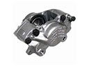 Toyota Tundra Brake Caliper
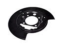 Toyota Tundra Backing Plate
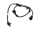 Toyota Tundra Speed Sensor
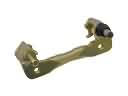 Toyota Tundra Brake Caliper Bracket
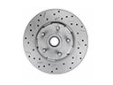 Toyota Tundra Brake Disc
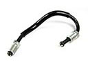 Toyota Tundra Brake Line
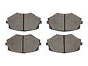 Toyota Tundra Brake Pad Set
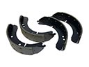 Toyota Tundra Brake Shoe Set
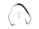 Toyota Tundra Hydraulic Hose
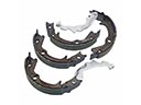 Toyota Tundra Parking Brake Shoe
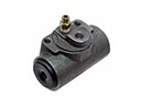 Toyota Tundra Wheel Cylinder
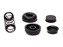 Toyota Tundra Wheel Cylinder Repair Kit